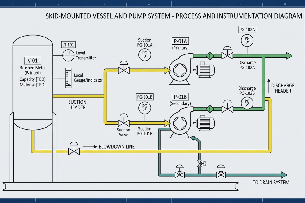
The chemical industry depends on various types of documentation to operate facilities safely and to protect the integrity of processing equipment. The Piping and Instrumentation Diagram (P&ID) is the foundation of many such documentation sets. Individuals working in the chemical process industries in Gujarat, from the large scale refining facilities in Dahej to smaller specialty chemical facilities in Ankleshwar, are required to have an understanding of symbols used on P&IDs.
Water and various other chemicals are pumped long distances within a chemical plant. Intermediate as well as final chemical products are moved within and between processing units by pumps. Thus, the knowledge of pump symbols used on P&IDs is essential for process engineers.
What are P&ID Symbols For Pumps?
A Piping and Instrumentation Diagram (P&ID) is a blueprint of a process plant that shows plant process and plant service piping systems and related instruments and control devices. A P&ID is a diagram of a process plant and often shows thousands of equipment items. Each of these items has a specific representation on the diagram using standardized graphic symbols. A symbol for a pump on a P&ID represents an item of equipment that is provided to move a process fluid.
P&ID symbols represent detailed engineering information. A correctly drawn symbol indicates the type of pump, the position of the pump in relation to the process, how the pump is driven, and where the pump is connected in the process.
Types of P&ID Pump Symbols
Many different types of fluids are processed by the chemical industry, from water to air to very high and very low molecular weight materials. Chemical engineers must design processes to transport these various fluid streams and select suitable types of pumps for these services. These various designs must be portrayed in a Piping and Instrumentation Diagram (P&ID).
- Centrifugal Pumps: The workhorses of the processing industry are centrifugal pumps. The symbols for these types of pumps show up easily on P&IDs, as these pumps are ubiquitous on process facilities. Centrifugal pumps are shown with a circular symbol, with suction and discharge lines entering the circle from the side and top, respectively. Because facilities use these pumps for over 80% of their fluid-moving needs, recognizing the symbol for centrifugal pump operations is the first step in P&ID literacy.
- Positive Displacement Pumps: Symbols for other types of pumps, such as positive displacement pumps, are shown with non-standard graphics to represent the mechanical action of the pump. Positive displacement pumps are shown with geometric shapes superimposed on one another and/or with lines representing waves to represent the mechanical action of the pump.
- Vacuum Pumps: Vacuum pumps and compressors, which are very similar, differ in that vacuum pumps show internal arrows or other graphics to represent that the pump is designed to remove gas to create a partial or total vacuum.
Components of Pump P&ID Symbols
A P&ID symbol for a pump shows only a part of the story. It contains numerous elements that describe an entire piece of equipment.
- Pump Type and Casing: The main element of the symbol is a circle that denotes the type and location of the pump’s casing and the type of impeller.
- Power Source: A circle or box that represents a power source is shown attached to the pump. This element may also represent a steam turbine.
- Equipment Tag: All equipment is assigned a unique number. In a P&ID, this number is shown on the equipment tag. The equipment tag is a link to the plant’s records, logs, and maintenance records.
- Lines and Nozzles: Lines in a P&ID show the direction of flow of the process medium. Nozzles, also known as equipment connections, represent the inlet and outlet of equipment.
How to Read Pump Symbols?
Reading a P&ID requires a systematic approach. When you encounter a pump on a diagram, follow these steps to extract the necessary information:
- Identify the Tag First: Locate the pump tag. The letter “P” universally denotes a pump, followed by the unit and equipment number. An “A/B” suffix usually indicates a primary and standby pump configuration, a common reliability practice in Gujarat’s continuously operating chemical hubs.
- Determine the Pump Type: Look at the main geometry. Is it a standard centrifugal pump symbol, or does it feature the dual rotors of a gear pump?
- Trace the Flow Path: Follow the solid lines entering and exiting the pump. Ensure the suction line features the necessary block valves and strainers, and verify the discharge line includes a check valve to prevent backflow.
- Check the Driver: Identify what powers the pump to understand the utility requirements (electrical vs. steam).
Guidelines to Prepare P&ID for Pumps
A P&ID consists of hundreds of lines and symbols and requires great precision and adherence to standards. Process engineers translate these diagrams to create plant designs and illustrations of operable processes.
- Piping Geometry: To eliminate vapor pocket formation and cavitation in a centrifugal pump, the eccentric reducer in the suction line must be drawn in a flat position.
- Isolation and Protection: Provide block valves on both lines to isolate the pump for maintenance and protect the pump from the effects of a collapsed suction. A check valve in the discharge line prevents water hammer and protects the pump from being driven backwards.
- Drains and Vents: For chemical pumps, provide vent and drain valves on the pump casing. The vent valve must be shown on the top of the pump casing, and the drain valve on the bottom.
- Minimum Flow Bypass: For a high-energy pump, provide a means for recirculating a minimum flow to prevent pump overheating.
Best Practices When Reading or Creating Pump Symbols in P&IDs
To be safe and efficient, most agree that consistency is key. So to promote consistency, industry organizations (e.g. the International Society of Automation (ISA) and Process Industry Practices (PIP)) publish guidelines that standardize how information is presented in process control engineering drawings.
In general, in-house drawings and symbols should be avoided because contractors, and auditors, for that matter, will find them confusing. Furthermore, employees at all levels should be continually trained. Particularly, new designers should be trained to create process control drawings and taught how to use the latest process engineering design tools.
There are many educational opportunities available. For example, a process engineer course can help you learn the skills necessary to develop process and control drawings, as well as other advanced process engineering skills. Institutions like Energy Learning in Gujarat provide excellent frameworks and specialized training modules that help engineers master complex industrial diagrams and equipment specifications.
The Role of Multidisciplinary Engineering in P&ID Development
A P&ID represents the combined efforts of many engineers on a project. The process engineer establishes the hydraulic requirements of a process and the properties of the fluids involved. The mechanical engineer uses this information to physically size the pump and restricts the size of the pump represented on the drawing. Finally, the instrumentation and control engineer positions, installs, and designs the control systems for the pump, as well as other sensors represented on the P&ID.
With the contribution of all the disciplines on the project, it is ensured that the final P&ID captures process automation and control systems.
Why are P&ID Pump Symbols Important?
Pump symbols have a significant impact on the safety and functioning of a chemical plant. During an analysis of a Hazard and Operability Study (HAZOP), the engineering team focuses on pump symbols and helps to find potential plant failures. Often, an analysis of a pump symbol helps to recognize a potential backflow. This analysis can help to identify if a pump is operating beyond its design limits and can help to find if a system is operating outside its limits. Sometimes, omission of a check valve on a pump symbol can lead to a team being unaware of a significant back flow problem and can result in equipment failure and a release of chemicals being processed by the plant.
P&ID diagrams are also essential to plant operations to help shutdown or isolate equipment. Inaccuracies on a diagram can lead to a long and unnecessary shutdown of a plant. This is particularly critical if the plant works with hazardous material, and is located in a densely populated area.
Final Words
Adequate knowledge of P&ID symbols for pumps is vital to a process engineer in the oil and gas industry. Correct use of the centrifugal pump symbol as well as assignment of pump tags carries operational significance. Documentation of process designs, fabrication and construction of process facilities ought to be accurate and safe.